Zeroing the Z Axis with a live micro-tool
Coding the Toolpath
Setting "Z" zero for micro-tools with diameters less that 0.0313" (0.8mm) can be challenging because it can be difficult to see when the tip of the spinning tool actually touches the surface of the material you want to cut.
The following technique, originally used by John Torrez (Think & Tinker, Ltd) cuts a small, highly visible circle in a "step and repeat" pattern along the Z-axis to safely "find" the top of the material. The technique was improved and coded by Milo Scott (Milo Scott Studio) who modified the code to reset Z=0 every time the code is run (more on this later).
To code the toolpath, we used Vectric Aspire, although any other CAM software could be used.
For this code to function properly, it is essential that your CNC controller supports the G92 (Set Z=0 command)
In the following example, we will be setting up on the TOP surface of the material. Although not strictly necessary, it makes the process of setting Z=0 more straightforward and less prone to error.
- Set X0Y0 to be the center of the circle .
- Create a 0.25" circle centered around X0Y0
Create 2D toolpath
- Set PASS DEPTH = 0.001"
- Tool = Test tool
- MACHINE VECTORS = "ON".
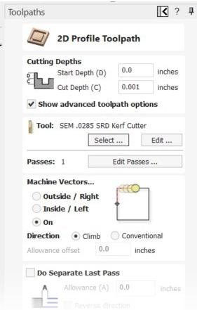
- Calculate Toolpath and save to file.
- Open the G-code file in a text editor (e.g. NOTEPAD)
- Code needs to be added after the last move of the circle, before the G0 that lifts the spindle (line with light RED background).
- Add "G92 Z0" to reset the Z=0.00 position (line with light GREEN background).
- Save the modified code and transfer to the CNC
Note: You may have to change the header and tool description information to work with your CNC controller!
The code is now ready to RUN
Sample G-Code
// VECTRIC POST REVISION// 051D7699EEB9AF1C94E4D27DF4D6F58C
// 001 Step
// File created: Thursday March 13 2025 - 02:40 PM
// Milo PP= Legacy 3Ax DELTA 20250204 {*.nc}
// Job Size X= 1.000, Y= 1.000, Z= 0.500
// Z Max Depth = 0.000
// Z Zero= Material Surface
// Location 0/0= Center
// Location X Offset= 0.000, Y Offset= 0.000
// File Notes:
// Tools used in this file:
// 1 = SEM .0285 SRD Kerf Cutter
// Toolpaths used in this file:
// 001 Step
G00G20G17G90G40G80G64G98G50G69G50.1G49
G90 G0 G53 Z0
//Toolpath: 001 Step
M6T1 //Tool: 1 = SEM .0285 SRD Kerf Cutter
G43H1
S24000M3
//Toolpath Notes
G0 X0.0000 Y0.1250
G0 X0.0000 Y0.1250 Z0.1000
G0 X0.0000 Y0.1250 Z0.0100
G1 X0.0000 Y0.1250 Z-0.0010 F72.0
G2 X0.1250 Y0.0000 I0.0000 J-0.1250
G2 X0.0000 Y-0.1250 I-0.1250 J0.0000
G2 X-0.1250 Y0.0000 I0.0000 J0.1250
G2 X0.0000 Y0.1250 I0.1250 J0.0000 //Last move in circle
G92 Z0 //Added to Reset CNC Z Zero
G0 X0.0000 Y0.1250 Z0.1000
M5
G90 G0 G53 Z0
M30
Finding Zero
With the code finished and tested in "air cutting" mode, you are now ready to find the surface. Remember to make sure that the spindle turns on before any cutting is attempted. The process proceeds as follows:
- Move your spindle over a point outside your design and lower it until the tip of the tool is about 0.5" above the material.
- Using a pencil or marker, CAREFULLY color in a dark spot large enough to contain a 0.25" circle. You can also color in the spot first and then move the tool into position. Just make sure you are centered on the spot.
- Lower the tip of the tool until it is very close to the material. Shining a flashlight from the side will help you see when the tip very close to, but not touching, the surface.
- Set the CNC controller to Z=0.
- Run the code.
- The spindle turns on and drops to the current Z=0. (For this first cut, the spindle is already at Z=0, so this step is ignored.)
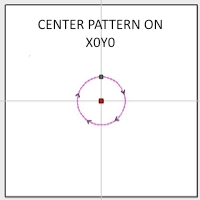
- The spindle drops 0.001", "cuts" a 0.25" dia. circle
- At the end of the cut, the code sets the new Z position in the controller to Z=0.
- The spindle turns off and lifts to the safe height defined in the controller.
- Examine the spot.
- If the dark spot on the material is undisturbed, run the code again
- If the dark spot is only partially marked, run the code again
- Re-run the code as many times as necessary to find the top surface of the material.
- If the dark spot shows a full circle, Z=0 has been successfully set.
- You system is now ready to make chips.
Note: To prevent the possibility of over cutting, or cutting too deep, you might want to lift the spindle 0.001" and set a new Z=0, but this is generally not necessary.
Finding Zero
video courtesy of M. Scott, Milo Scott Studios