Finding the Sweet Spot When Machining with Carbide Microtools
The first question that most people ask when using carbide mini and micro tools to cut wood (and other soft materials) for the first time, is, "What are the best speeds and feeds?". What they really want to know is, "How fast I can cut without breaking a bit? What are the optimum cutting conditions with my equipment?" If you are primarily cutting metal, in most cases, the process of selecting the proper speed (RPM) and feed-rate is relatively straightforward. If you are cutting woods or plastics, the world is not so kind. Nonetheless, it is possible to arrive at an optimum combination of speed and feed reliably and repeatably without experiencing too much brain-death.
The following discussion assumes that:
- SPEED always refers to spindle RPM
- FEED always refers to how fast the cutter moves through the material or how fast the table moves during a cutting operation (also referred to as "feed rate")
- you have measured the backlash on both the X and Y axes of your CNC router and both are less than 0.001" (0.025mm)
- material density and abrasiveness
- material homogeneity (consistent density and cutting properties from point to point)
- feedrate ramp (or acceleration)
- feedrate
- spindle RPM
- spindle TIR
- Clean the spindle bore and collets with ColletCare
- Measure the TIR of the collet you will be using for the test
(measured as far down on the calibration blank as possible) - Use the controller interface to set the acceleration on each axis
(excessive acceleration may break the tool prematurely) - Determine the highest RPM that you can use to cut the material you are testing with this tool
- Record this data for later use
Over the past 20+ years we have gathered a LOT of data cutting specific materials. You can find the information at:
- Mother-of-Pearl (MOP)
- FR-4 / G10

We consider the feedrate (FEED) and the spindle RPM (SPEED) together because, in the case of cutting soft materials like wood and plastic, it is their combination into a single parameter known as "CHIPLOAD" that matters the most. As the name suggests, chip load is the amount of material (load) each flute cuts during each revolution (every chip). Another way of looking at it is how far the bit chews into the material every time it rotates one full turn. As the chip load increases (bigger bite per revolution), the transverse stress on the tool increases. Clearly it is important to keep the strain, that results from this stress, below the breaking point of the tool (Transverse Rupture Strength (TRS). On the other hand, at very low chip loads, not much material is being cut so there is nothing to carry heat away from the cutting edges. Below a certain limit, the tools gets too hot and abrasion rolls away the cutting edge, rendering the bit useless. In the case of machining thermoplastics, feed rates that are too low also inevitably lead to the swarf (stuff that you just cut) melting together, which can clog up the flutes and break the bit. Usually the breaking point is preceded by the chips melting and packing together in the kerf as the bit moves on. There is another aspect to chip load that is often overlooked. As the bit turns and starts to cut, material "flows" across the outside and inside faces of the cutting flutes. If this material "flow" is too high on the outer surface (low chip load) the cutting edge rounds over from material abrasion. If the material "flow" is too high on the inner surface (high chip load) the cutting debris cannot be evacuated quickly enough causing it to back up and pack. With nowhere to go, the impacted material seals off the flute and the bit breaks. When the outside and inside "flow rates" are balanced, edge erosion is symmetric and the bit stays sharper longer. We call this the "Sweet Spot". This near mystical combination of FEED and SPEED is exactly what we are trying to find. The strategy that we will employ is pretty simple-minded. Using the SPEED determined above, we will make a series of cuts at gradually increasing FEED rates and examine the chips and kerf produced at each step to find the sweet-spot. The characteristics of the sweetspot in both woods and plastics share some common features.
- If your feed to too low for the spindle speed, the chipload is too small. In most woods, the swarf will be a fine powder that will tightly pack the kerf and have to be picked out by hand. You might also see some burning in the corners where the bit changes direction. In a thermoplastic, this is the region where the chips are so hot that they melt together and weld back to the parent material basically ruining the workpiece. There is also a VERY good possibility that you will break the bit.
The sidewalls of the kerf will probably show a fair amount of chatter (if you can remove the debris)
- If your feed/speed combination is just right, wood and plastic swarf will come out as nicely formed chips with little or no packing in the kerf. You should be able to blow out any debris with low pressure air.
The sidewalls and top edges of the kerf should be fairly smooth showing only minor tool marks.
- If your feedrate is too high for the spindle speed, resulting in a chipload that is too much for your cutter to accommodate, the bit will start to chatter as the flutes become filled with swarf faster than it can be ejected. You can usually see this happen quite a while before the lateral forces break the bit.
The sidewalls and top edges of the kerf will start to show significant chatter marks. In the case of brittle plastics, you might also witness material being fractured out of the top edges.
To make sure that we choose a safe starting place, we always some empirical "rules of thumb" to set the depth of plunge, initial feedrate and feedrate increment. In the list below, D is the diameter of the bit being tested.
- Softwoods like pine or fir (Janka < 1,000): Z = 2 x D
- Hardwoods like birch, cherry, maple or rosewood (1,000 < Janka < 2,500): Z = 1 x D
- Extreme hardwoods like ebony and ipe (2,500 < Janka < 5,00): Z = 0.5 x D
- Composites like G10, paper phenolic or carbon fiber: Z = 1 x D
- Thermoplastics like PVC, ABS, acrylic or polycarbonate: Z = 1 x D
- Softwoods like pine or fir: F = 0.03 x D x No. flutes x RPM (3% chipload per flute)
- Hardwoods like birch, cherry, maple or rosewood: F = 0.03 x D x No. flutes x RPM (3% chipload per flute)
- Extreme hardwoods like ebony and ipe: F = 0.03 x D x No. flutes x RPM (3% chipload per flute)
- Composites like G10, paper phenolic or carbon fiber: F = 0.007 x D x No. flutes x RPM (0.7% chipload per flute)
- Thermoplastics like PVC, ABS, acrylic or polycarbonate: F = 0.08 x D x No. flutes x RPM (8% chipload per flute)
- Softwoods like pine or fir: ΔF = 20 IPM (0.51m/min)
- Hardwoods like birch, cherry, maple or rosewood: ΔF = 10 IPM (0.25m/min)
- Extreme hardwoods like ebony and ipe: ΔF = 10 IPM (0.25m/min)
- Composites like G10, paper phenolic or carbon fiber: ΔF = 5 IPM (0.13m/min)
- Thermoplastics like PVC, ABS, acrylic or polycarbonate: ΔF = 5 IPM (0.13m/min)
For the sake of simplicity, and uniformity in data collection, all of our testing will be done with the plunge depth specified above. Before you cry foul and point out that most "real world" machining involves much deeper material removal, keep in mind that our goal is to investigate as many feed / speed combinations as possible WITHOUT breaking the bit. By plunging D deep into the material under test, we minimize the stress on the bit and reduce the chance that it will break. Of course, in actual practice, you can plunge much deeper but, you should keep in mind that the relationship between feedrate and depth of cut is often VERY non-linear. You may find that is it much faster to make a lot of shallow, high-feedrate passes than to make a single deep pass. It is definitely much kinder to your bit and spindle bearings.

- Program a set of parallel slots 1" long and spaced apart at least 2 times the diameter (D) of the bit that you are testing (S = 2 X D) using the test FEED determined above as a starting point.
- Set up your router/spindle to the "quiet" SPEED also from above.
- Plunge the bit 1 diameter (1 X D) deep (e.g. plunge a 0.0625" dia. tool, 0.0625" deep)
- Cut the first 1" slot.
- Pick up the tool, move to the top of next slot.
- Increase the feedrate by ΔF:
- ΔF = 5 IPM (inches per minute) for tools less than 0.0315" (0.80mm)dia
- ΔF = 8 IPM (inches per minute) for tools greater than 0.0320" (0.81mm) but less than 0.1181" (3mm).
- ΔF = 10 IPM (inches per minute) for tools greater than 0.1250" (3.18mm) dia.
- Note: As you gain experience, you will probably select different ΔF values to more precisely determine the best FEED to match your SPEED. We typically run a test with a fairly large ΔF to isolate the general neighborhood of the sweet spot, then set a lower ΔF to home in on the best operating point.
- Cut the second slot.
- Pick up the tool, move to the top of next slot.
- Again increase the feed by ΔF.
- Continue in this fashion until one of two things occurs.
- the quality of the cut starts to markedly deteriorate or,
- the bit breaks.
- Whichever happens, stop the test and record the feedrate (Fmax) where the bit started to fail.
- Multiply Fmax by 0.75 to get the sweet spot for these cutting conditions.
- Record the sweet spot information in your shop log, listing the material, tool specifications, depth of cut, RPM, and optimum feedrate.
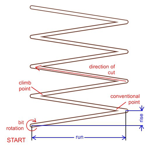
Todd Reith (Custom Luthier / Reith Guitars) offers a very valid objection to the testing scenario above. He points out that lifting the tool between each cut does not accurately reflect the cutting dynamics encountered in most machining operations. Another problem is that it ignores the fact that, in materials like wood that have different cutting properties in different directions, the test does not accurately model what happens in a real wood cutting process. After trying a number of different cutting strategies, we have found that a simple "zigzag" offers an excellent combination of being easy to program, accurately representing real-world cutting, and offering a clear differentiation between climb and conventional cutting.
Proceed as follows:
- You will be cutting a simple zigzag pattern oriented any way you like relative to the grain (if any) of the material that you are cutting.
- The size (RUN and RISE) of the pattern that you program depends, in large measure, on the diameter of the tool you are testing. Practically speaking, we never use a pattern with a RUN (see image on left) less than 1 " (25.4mm) wide for tools 1/8" (3.18mm) dia and smaller or less than 2" (51mm) wide for tools 1/8" (3.18mm) to 1/4" (6.4mm) dia..
- You will calculate the RISE based on your cutter diameter. We never use a rise that is less than 2 times the cutter diameter (2X dia). If the material we are testing is fairly narrow, and we want to run several different tests, we will increase the RISE so that we can interleave the patterns together in a herringbone pattern.
- Set the RPM on your router/spindle to the "smooth" nodal SPEED found above
- As a starting point, use the test FEED calculated above.
- Plunge the bit 1 diameter (1X dia) deep (e.g. plunge a 0.0625" dia. tool, 0.0625" deep) and zig to the right and zag back to the left.
- Increase the feedrate by ΔF:
- ΔF = 5 IPM (inches per minute) for tools less than 0.0315" (0.80mm) dia.
- ΔF = 8 IPM (inches per minute) for tools greater than 0.0320" (0.81mm) but less than 0.1181" (3mm) dia.
- ΔF = 10 IPM (inches per minute) for tools greater than 0.1250" (3.18mm) dia.
- Note: As you gain experience, you will probably select different ΔF values to more precisely determine the best FEED to match your SPEED. We typically run a "ranging" test with a fairly large ΔF to isolate the general neighborhood of the sweet spot, then set a lower ΔF to home in on the best combination of FEEDs and SPEEDs.
- Cut the next zigzag
- Again increase the feedrate by ΔF.
- Continue in this fashion until one of two things occurs.
- the quality of the cut starts to markedly deteriorate or,
- the bit breaks.
- Whichever happens, stop the test and record the feedrate (Fmax) where the bit started to fail.
- Multiply Fmax by 0.75 to get the sweet spot for these cutting conditions.
- Record the sweet spot information in your shop log, listing the material, tool specifications, depth of cut, RPM, and optimum feedrate.
The beauty of this method is that it more accurately models normal cutting modes by leaving the flutes in the material. This accounts for the heat that builds up as material is removed and reproduces many of the variable stresses that the tool is exposed to during normal operation. An added value is that the zigzag pattern isolates the effects of climb cutting around a sharp corner (left side) from the effects of conventional cutting (right side). This will be expanded upon in later tutorials where the condition of these sharp corners provides a very unambiguous sweet spot indicator.

In many materials, you will notice an obvious reduction in the quality of the cut as the feedrate becomes too high. This is because the chip load (amount of material being cut by each flute) starts to exceed the available space between the flutes, causing the swarf to pack and interfere with the cutting action.
Look for:
- splintering / burring along the top edge
- bit chatter, especially along the climb side of the cut
- chipping of the top edges in hard plastics
- significant deflection and tip "wander" (sometimes looks like a shallow sine wave in long straight sections)