Measuring spindle runout with a dial test indicator
Overview
Crappy cuts and broken bits are no fun.
In addition to the cost of a broken cutter, you often have to add in the time and material cost for the part you just ruined. Remember. "Murphy is your shepherd" (Tom Larcombe). A bit will almost always break in the worst possible place, at the worst possible time and a bad cut will almost always take off more material than intended.
One of the leading causes of bit chatter and breakage on CNC routers is excessive runout or eccentricity at the cutting tool (aka TIR - Total Indicated Runout) As reported a number of years ago, excessive runout of the spindle, collet or cutting tool (or any combination thereof), can have a significant impact on the life of carbide tools and of the spindle itself. In a test of solid carbide drill bits, improving TIR from 0.0006in. (15µ) to 0.00008in. (2µ) tripled tool life. Ironically, in the survey, the average tool user considered 0.0005in. (13µ) TIR to be acceptable.
While researching the source of runout in the consumer-grade routers used in entry level CNCs, a surprising fact emerged. Most of the motors used in the low-cost (<US$150.00, circa 2010) routers and laminate trimmers that we tested were actually quite good (TIR < 0.0003 in. (8µ) measured inside the tapered chuck bore). However, most of the the stock collets and collet reducers were just plain junk (measurements ranging from 0.0030 in. (76µ) TIR to 0.0100 in. (254µ) TIR). Note that TIR = 0.003in (76µ) is enough to snap off a 0.0313 in. (0.8mm) carbide micro-tool, even under a low to moderate chip load.
The aluminum collets found in many hand grinders were the worst of all with TIR measuring as high as 0.0150 in. (381µ)

Measuring Spindle Bore TIR
The cut quality produced by a spindle (or router) based CNC is a combination of many factors with every component; the spindle bore, spindle bearings, tool holders, collets, collet nuts, tool-shanks and flute grinds, making a contribution.
When trouble shooting cut quality and bit breakage issues, the first component to consider is the concentricity and fidelity of the tapered bore at the end of the spindle armature (sometimes called the "chuck". This measurement will quantify the sum of the contributions from the bearings and the ground surface of the tapered bore. If the runout of the spindle bore is excessive, adding certified high-precision collets is unlikely to solve your cutting problems. It is no more than putting lipstick on a pig. That is why, before you go shopping for new collets (or new tool holders, if you have an automatic tool changer), you should measure the spindle bore to insure that it is turning true (TIR < 0.0001", 2.54µ).
Measuring the TIR of the bore is quite straight forward if you have access to a "Dial Test Indicator (DTI)" (NOT a Dial Indicator) with a resolution of at least 0.0005 in.(12.7µ) (0.0001 in. (2.54µ)) is preferred). If you don't have one, go buy one. If you are on a budget and can wait for a couple of weeks, go to eBay and search under "test indicator". Starret, Fowler, Mitutoyo and Accusize are brands to look for.
To determine the fidelity of the bore, you will need to make measurements in 2 positions; the mouth, where the bore is largest and waist, where the bore is the narrowest and the tapered grind ends.
If you are new to using a DTI, a good tutorial from the Haas company can be found at How to Use a Test Indicator
Before starting this procedure, please take time to properly clean the spindle bore with a suitable solvent/lubricant!
Before starting the measurement, preheat your spindle to running temperature. The internal construction of the spindle motor requires that the bearings be VERY warm to provide the axial preload esential for concentric running.
It will be easier to accurately record the necessary measurements if you wrap some masking tape (or other light colored tape) around the threads (not shown in this example).
TIR at the Mouth
To make a measurement at the mouth, position the ball of the indicator stylus above the chamfer that is found at the mouth of virtually all spindles and consumer routers (it is an artifact left over from grinding the bore, see fig. 1). You are ready to start the measurement.
- Using the adjustment knob on your magnetic base, move the stylus against the face of the bore and load it until the needle moves about 90° in the clockwise (CW) direction to position the indicator in the middle of the DTI measurement range. This should give you enough range for the measurement you will be making.
- With your fingertip on the back of the threads, LIGHTLY roll the spindle armature one full rotation, making note of how far needle moves in the counter clockwise (CCW) direction. We will refer to this as the "low spot".
- Roll the armature slightly back and forth to accurately find the low spot.
- Use the adjustment knob on the mag base to position the needle over the "0" (zero) on the DTI dial face.
- SLOWLY rotate the armature until the needle reaches its maximum deflection from 0.
- Record this value. It is the TIR of the bore as measured at the mouth.
- If you have wrapped light colored tape around the threads, use a marker to put a black dot on the tape just above the mouth aligned with some convenient reference on the spindle.
Measuring TIR at Mouth of Bore
image courtesy of S. Rosburg
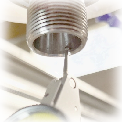
fig. 1
TIR at the Waist
To make a measurement at the waist of the bore, position the ball of the indicator stylus as far up into the bore as possible. Make sure that the stylus tip is still on the smooth surface of the tapered bore and that the DTI body is not rubbing the mouth of the bore!
- Again, using the adjustment knob on your magnetic base, move the stylus against the face of the bore and load it until the needle moves about 90° in the clockwise (CW) direction.
- With your fingertip on the back of the threads, LIGHTLY lightly roll the spindle armature one full rotation, making note of how far needle moves in the counter clockwise (CCW) direction. As above, we will refer to this as the "low spot".
- Roll the armature slightly back and forth to accurately find the low spot.
- Use the adjustment knob on the mag base to position the needle over the "0" (zero) on the DTI dial face.
- SLOWLY rotate the armature until the needle reaches its maximum deflection from 0.
- Record this value. It is the TIR of the bore as measured at the waist.
- Use a marker to put a black dot near the top edge the tape aligned with the same reference on the spindle used above.
Measuring TIR at Waist of Bore
image courtesy of S. Rosburg
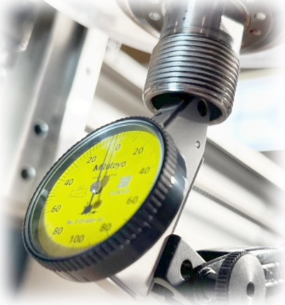
fig. 2
What do these measurements mean?
How do you use the data you have just gathered to determine if your spindle is good enough to use for precision work with microtools? For the most part, it is pretty straight forward.
- If the TIR measured at the mouth is equal to, and lined up with the TIR at the waist, the runout is purely radial and will be constant, no matter how far down you are from mouth. As long as the measurement is in the neighborhood of 0.0001in. (2.54µ), but less than 0.0003in. (7.6µ), the spindle is suitable for use with microtools.
- If the measurements at the mouth and waist are not equal, not lined up, or both, things get a bit more complcated. In these cases, you have a combination of radial and angular runout (see "What is Runout" above). Such a combination will cause the TIR to change (probably increase)as you move down from the mouth of the bore. If the change is slow enough that the combined runout at a point 0.80 in. (20.3mm) below your nut is less than 0.0002 in. (5.8µ), when using a high-precision collet, the spindle is suitable for use with microtools (see Measure Combined Spindle/Collet TIR below).
- If the combined TIR measured with a high-precision collet is greater than 0.0005 in. (12.7µ), you might still be able to use the spindle with microtools if you restrict operations to low chiploads (feed rates) but this will significantly reduce the life of the cutter.
Measuring Combined Spindle / Collet TIR
To start, load a calibration blank (or a broken bit with at least 3/4 inch of smooth shank) into the collet. You need a straight, smooth shank to perform this measurement. The more the shank sticks out of the collet, the more any eccentricity will be magnified, but you need at least 1/2 in. inside the collet to insure that the bit is properly seated.
Clean the exposed shank of any debris by dabbing it with tacky putty. Silly Putty also works pretty well.
Position the ball tip of a dial test indicator as close as possible to the center line of the the shank and as far down on the shank as you can get (unless you are using a calibration blank, in which case, position the stylus as close to the collet face as you can get without rubbing.).
Pre-load the DTI stylus against the shank until the blank is in the middle of the movement range of the stylus. We do not recommend using the jog on your CNC since an accidental rapid movement that exceeds the range of the indicator can permanently damage its internal mechanism.
Rotate the spindle armature with very light finger pressure on the collet nut until you find the MAXIMUM rotation of the needle in the counter-clockwise (CCW) direction.
Carefully rotate the face of the DTI until the needle is aligned with zero "0".
NOTE: With a sensitive instrument, exact positioning can be quite difficult so don't obsess about it. Record the position of the needle (0.0005 in. in fig. 1) to offset the measurement below.
Place a white dot on the forward facing facet of the collet nut to mark your starting position.

Again using light finger pressure on the back of the nut, rotate the armature in the until your find the orientation that gives MAXIMUM deflection to the needle.
Record the amount indicated on the dial. (0.0055 in. in the fig. 2) and subtract the offset (0.0005in) from above since both readings are on the same side of the dial zero "0".
The measurements shown in these pictures reveal that this spindle / collet combination has 0.0050 in. (0.127mm) TIR making this spindle / collet setup unsuitable for CNC machining with most micro-tools.

Assuming that you have a long enough calibration blank, move the probe of the test indicator to a point at least 0.80in. (20.3mm) from the face of the collet and repeat the above steps. In many respects, this is the most important measurement because most micro-tools stick out of the collet from 0.50in. (12.7mm) to 0.80in. (20.3mm) , so this is where most of the machining is going to take place in a multi-pass cut. Excessive TIR here can show up in the finish of your final product and / or with a broken bit.
Record the TIR measured at both locations and the approximate angle (phase angle) between them (think of TIR as the hands of a clock that stick out from the true center of the axis of rotation). If the max TIR at both positions on the calibration blank are on the same side of the bit, most of your eccentricity is caused by the collet bore being slightly off-center (offset or radial TIR). If there is a significant angle between them, most of the runout is caused by the collet bore being at an angle relative to the axis of rotation (skew or angular TIR). This is the worst type to have because it makes the TIR grow larger as you move out from the collet face.
The moral of this story is, "Before you start cutting, measure the combined runout of your spindle and collet!". Even though you might be itching with impatience to get out in the shop and cut some wood with your new machine, breaking expensive bits is no fun at all (except, maybe for your tool vendor). Adding TIR determination to your standard set up procedure will save you a lot of headaches, and will help you come up to speed much faster.
For a more detailed discussion on the effect of TIR on system performance, please read the section on Selecting the Best Grade of Collet for Your Application.
Spindle TIR and Axis Orthogonality Measurment Toolset


The Mitutoyo based TIR Measurment Toolset makes the accurate determination of spindle TIR (Total Indicated Runout) and spindle axis orthogonality a straightforward and reliable process. These measurements are essential to the maintenance of accuracy, precision, and performance in CNC routers. Both are critical to cut quality, cut fidelity and tool life. The minimization of TIR pays added dividends by reducing the wear and tear on toolholders, collets and spindle bearings.
The Toolset incudes:
- Mitutoyo 513-406T Test Indicator (0.0005" res.) with clamps and tips
- Nogaflex Magnetic Base
We do not offer these items for sale, but you can find them online at: